
Still trying to figure a few things out, and came to an interesting thought. One of the character I want to animate with motion capture is a little forest/bush dwelling creature. And one of the things I'd like him to do is growl. Grrrr! And I thought, if he's going to growl (and make silly noises) I might want to have some sort of vibration occur over his mesh in the areas that might exhibit some sort of vibration movement; something like the mouth, nose and throat areas.
There are some things inside my 3D application that can do things like this, but none really have the control I was after. What I wanted was to vibrate the mesh by moving the mesh points along their vertex normals, using something like a vertex map to apply strength to the polygon points. I won't explain too much here, I'll simply put it like this: I just want to move points of polygons in certain areas up and down, using some frequency and strength controllers. And I want to be able to do this using something like a vertex map to control how much the vibration affects and which vertex points.
A vertex map is actually a good solution here, because you can paint the values of 0-100% on the mesh points and end up with exactly the kind of point control I'm after. I can easily paint on the character mesh to say how much the vibrations effect each area of the mesh with a vertex map. I can't find a wiki article on vertex maps, so I'll put an image of what one looks like below:
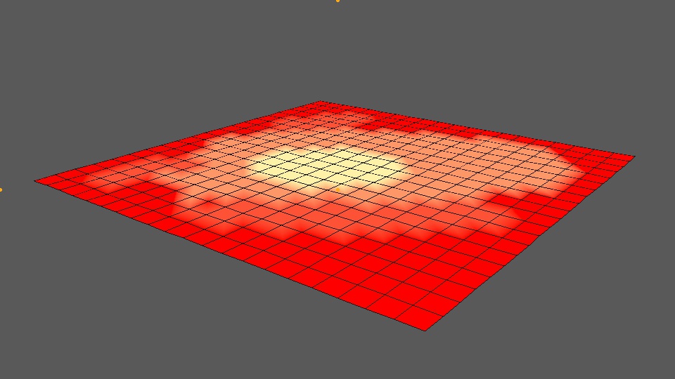
Just to briefly explain the image above, you can see a 20x20 flat polygon plane in the viewport, with a red-yellow texture 'painted' on it. In this instance, the colours represent a value between 0 and 100%. Red being zero, and yellow being 100%. The shading of yellow and red inbetween are values that lie inbetween, such as 40%, or 25%. The numbers themselves actually look like this 0.0, 0.2, 0.4 and 1.0 for 100%. If we paint on a vertex map, we can access these numbers.
So, there's a few things I have to sort out here. Firstly, I need to know the polygon mesh, it's polygons and point indexes. I need a vertex map (or something like that) to derive some sort of strength value. And I need to be able to calculate some normals for the polygon vertex points. Lastly, I then need 'some' formula that's going to produce the vibration offset (using something like a sine or cosine function). With all these, a maybe a couple of additional attributes, we should now be able to move the vertex points along their averaged normal direction. That's the idea, anyway!
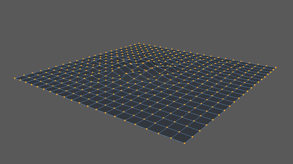
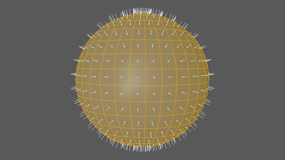
If you're not sure what all this means, in simple terms, I just want to make an object look like it's vibrating by oscilating the polygon points up and down. If you're not sure what the polygon points are, they are the orange dots in the image below:

And what we want to do is move these points up and down so they do things like this:
So, I built a tool to do just this. Here is the early user interface for it:
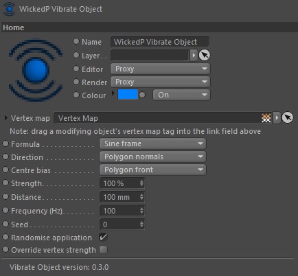
In the image above, we can see there's some controls and attributes for us to set. The most important one is the field for a vertex map. With this one, the user can drag a painted vertex map on their object into the link field. This will allow us to apply the vibration to only areas that are painted on a vertex map, using the vertex values - neat!
And - below is an early look of a render that shows two examples of the tool in action. The first example (the plane) was to test that it worked. The second example (the sphere) was to test that it works when polygons are in non-flat positions (like on the surface of a sphere!). In both tests we also want to see that the vertex points are being moved up and down along their calculated polygon normal average.
By the way, a normal is something that tells you which direction something faces. For 3D models, calculated normals might look something like this:
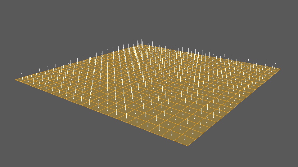
So, what we want to do is take those orange dots in the images above, and move them in the same direction the white lines are pointing. Here's a render of my new tool doing just that:
And another set of renders with variations to some of the settings:
I realised afterwards that the second video above hasn't got the renders in the correct colour space, that's why it looks darker. Oops! Sorry about that. Doesn't really matter here though. And finally, here's a render using a textured sphere:
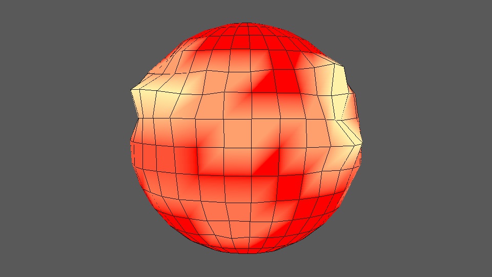
The tool seems like it works fairly well for a first pass. You can see that the point offsets are being driven by the strength of the red and yellow vertex maps. Red means there's zero strength, while yellow means 100% strength. Having a formula also means I can manipulate the offset movement even further, by using something like a sine or cosine wave to make the points look like they're moving up and down to a frequency.
I don't know much about writing formulas I must say, it's definitely not my coding strong point. But I did add in some formula selectors which allow the user to select either a sine or cosine function to further manipulate the offset values. It does this using the frame number, frequency and a strength setting. There's of course a distance setting, to tell the engine how far to offset the points (multiplied by the calculated strength). I can also limit the offset movements to the polygon front, rear, or centre them in both directions. There's also a seed number, which really only acts like a frame offset at the moment. But, it's there too.
It's a fairly simple tool, with simple workings. But one that might be handy during the animation process. I might even be able to use it for other mesh animations as well, such as for making ripples on a water surface, or flapping cloth in the wind, things like that.
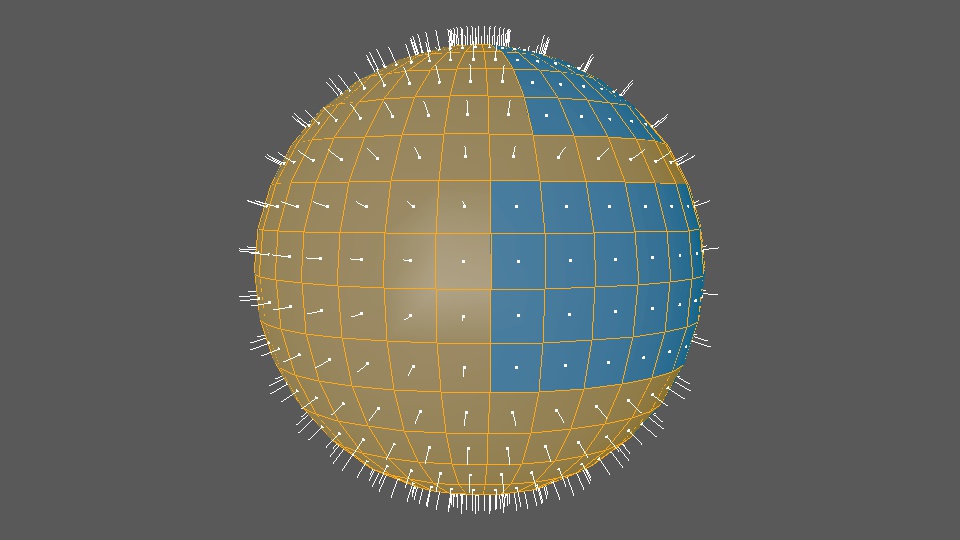
And, just for interest's sake, here's what the sphere's normals directions look like:
Normals can be reveresed as well - so they face in the opposite direction. Typically you'd always set your objects up so the normals face the same way. Normals are used in a few places, so they should be aligned correctly. For what it's worth, a sphere with a combination of correct and reversed normals might look like this:
And for completeness, here's the sphere with its vertex points moved in and out based on the vertex map values and the normals directions:
And thus ends the lesson on normals.
The only things I can see left to do now, are to work on the algorithms themselves. I currently have two, which are based on sine and cosine functions. I think both of these can be improved. And there's probably a few others I can source, and/or make up as well!
On another tooling note (!), I've almost completed adding my inverse kinematics engine into my ProxyMan tool. There's just a couple of small things to solve, which are mostly user and interface things, and then I should have a version with IK in it. This will be a bit of a moment for me when it happens, because it will give me a fairly good fundamental basis to animate and edit character motion capture on my own characters, using my own tools, in my own projects. Kinda cool really!
I'm still not sure how I'll do the facial motion capture yet. I don't like any of the 'off-the-shelf' solutions I've seen so far. They're either hideously expensive (why?) or just not good (clunky helmets with phone or GoPro camera mounts...). I know some of the latter style solutions might be a bit cheaper for the hobbyist, but I really don't like the idea of hanging a phone out in front of my face. They're too heavy and bulky. Not to mention they're right in your eyeline. So I may have to consider making my own solution somehow. But for now I'm not overly worried about the facial capture. If I need to I can probably make do with a simplified FACS system, or with plain old keyframe animation. Even if it's a little slower to begin with.
Things still to think about, and solutions still to find... And still no sign of my Optitrack motion capture system either! It's gone a few weeks past the advised arrival date now. But I'm not overly worried, just a little anxious to get my hands on it to keep moving things forward. I suspect the goings on in the Middle East are causing delays.